I was going to write some strong words about what has been going on in the world as of late, but for the moment, let's leave the icky, nasty world behind and look at something I don't write about as frequently: amateur radio.
Before I switched from WordPress back to a static blog, I had written about how I had been trying to build my own amateur radio stuff. While I am not dirt-poor, I just don't have the disposable income to buy even a used transmitter or transceiver right now.
I was blessed with a Heathkit SB-303 for my birthday a couple of years ago, but besides a couple of Baofeng HT's for VHF/UHF, that's pretty much my shack. I've had a few successes and mostly failures building working RF circuitry. My issue was/is that I don't have basic test equipment like an SWR meter, antenna analyzer or oscilloscope to check homebrewed circuits and antennas for proper tuning and signal purity. With that huge disadvantage, and the fact that I'm not some mega-super-RF-rock-star, it's currently difficult for me to make home-made amateur equipment.
Without access to must-have testing tools, I have scaled back my attempts to build home-made amateur stuff until I have the budget for at least an old o-scope or station monitor. Still having the 'itch' to use my soldering iron and work with electronics, I started to look for an inexpensive amateur radio QRP kit to build.
I took a look through the various QRP kit websites and didn't find anything that was in my price range, until I stumbled on a very inexpensive crystal-controlled transceiver that had a very small parts count being sold on eBay. Being under $5 USD (including shipping) I figured even if it was a complete failure, I'd have some extra capacitors, transistors and connectors to add to my collection. I purchased it and it arrived direct from China after a couple of weeks.
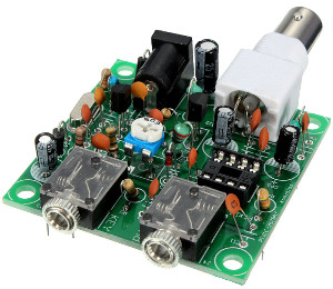
The Pixie 40-meter CW kit as shown on the seller's auction
When the kit arrived, it was in a small black plastic bag, surrounded by protective foam. It included a parts list with a close-up diagram of the circuit board, a schematic of the actual circuit, the circuit board and the components that comprise the transceiver. There are no instructions and some of the components were labeled in non-English, although anyone with electronics experience will probably be able to figure it all out.
(Sorry about some of the photos, my phone is very stubborn and doesn't like to take close-up pictures.)
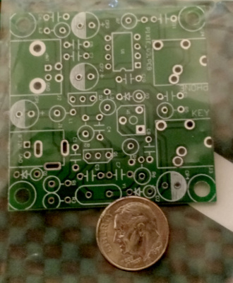
The Pixie circuit board with a dime for size-comparision
This kit is very small. When you look at the pictures on the auction, you might expect that the circuit board is a fair size, but as you can see from the picture above, it's pretty small. I imagine you could house the whole thing in an Altoids or similar tin like other QRP setups.
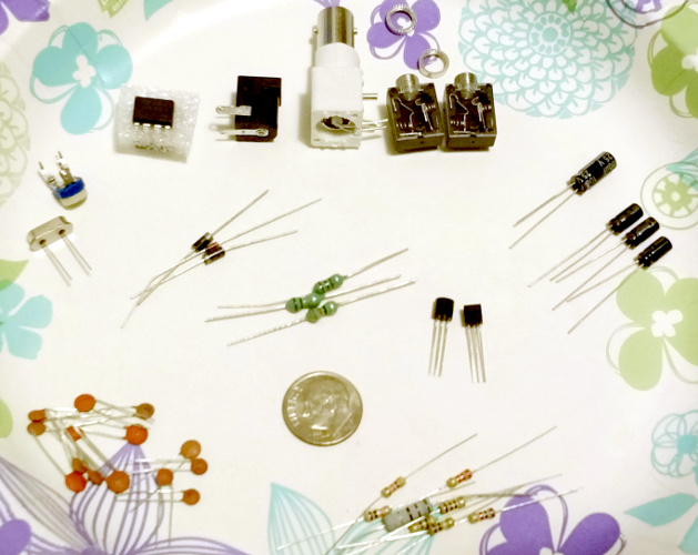
Kit components and a dime
The circuit board is fairly good quality while most of the components were, at least outwardly, of questionable quality. For example, the printing on some of the capacitors was almost illegible or distorted and at least one of the dipped inductors was really deformed. While the outward appearance of the components isn't an issue for me, it did remind me that the kit only cost less than $5 USD. Just as long as everything works, that's all that matters.
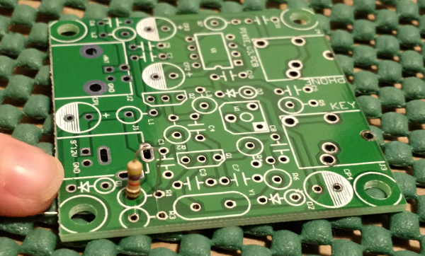
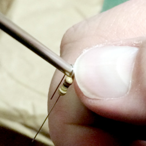
First component in! My four-year-old son points to the board.
Time to get down to business. After buffing the board lightly with a scrubber-pad and wiping it with alcohol, I followed the parts list and installed the components on the circuit board. I installed the semiconductors last so they wouldn't experience excess heat from the soldering of other nearby components. Basically I started with resistors, then the trimmer pot, ceramic capacitors, inductors, electrolytic capacitors, connectors and finally the semiconductors.
Making smooth bends for the axial leads. It's a personal preference.
I know it probably doesn't help much, but I like to make smooth bends on axial components. I was too lazy to find my smaller screwdriver, so the bends on this project were a bit larger than I would prefer.
With each component, I used my scrubber-pad to clean the grime from the leads so solder would flow better onto them. How bad or good the leads look depends on the practices of the components manufacturer and distributor, and since there were not that many components in this kit, cleaning each lead didn't add too much extra time to the project.
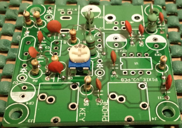
More parts in!
I was taking it nice and slow during the build. My four-year-old son was hanging
out, watching me and offering some momentary distractions so I wouldn't get burned-out
or bored. ![]() I installed a group of parts, turned the board over and soldered
them in, clipped the leads then started on a new group. I made sure to carefully
follow the parts list and only ended up with one forgotten component, which was
easily installed and soldered in.
I installed a group of parts, turned the board over and soldered
them in, clipped the leads then started on a new group. I made sure to carefully
follow the parts list and only ended up with one forgotten component, which was
easily installed and soldered in.
After everything was finished, I ended up with a few extra ceramic capacitors and one
higher-wattage 51 ohm resistor. I figured out that the extra resistor was
for hooking up to the antenna connector as a dummy-load. That's a nice extra, especially
for such an inexpensive kit. ![]()
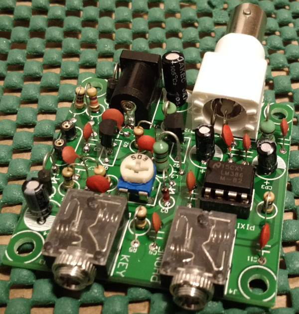
All done!
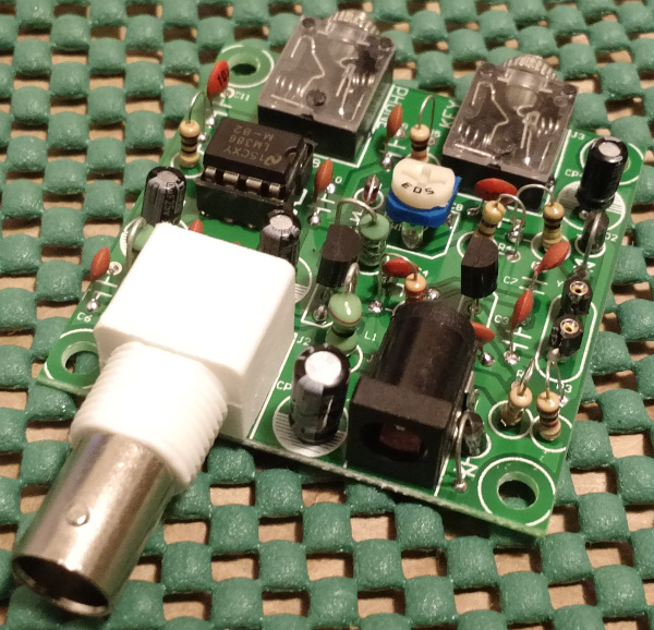
Other side
The kit comes with one 7.023 MHz crystal, which is okay, I guess, but 7.030 MHz is a QRP calling frequency, at least in the US. I found an amateur radio operator, KC9ON, selling six-packs of QRP-centric crystals that include a bunch of solder-post sockets for a very inexpensive price. KC9ON's eBay store is right here.
I installed two of the solder-post sockets from KC9ON into the crystal's location on the circuit-board. This will allow me to easily switch to any of the frequencies covered by my collection of 40-meter crystals in case one of the frequencies is in use or has bad interference. I don't recommend using crystals for other bands with this kit as-is because the kit is tuned for the 40-meter band -- for example, the low-pass filter starts attenuating around 7.2 MHz and higher.
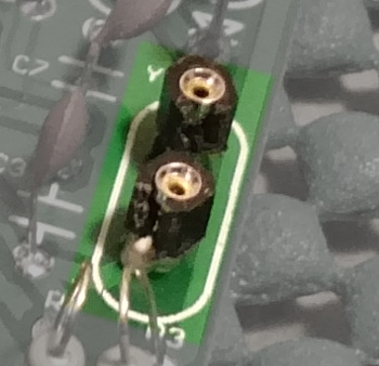
Crystal socket modification
With the building of the kit complete, I cleaned as much flux as I could off
of the solder side of the board and found a 9 VDC plug-in power supply
so I could give the transceiver a try. I plugged in my headphones and the power
supply and my eardrums almost exploded from the VERY LOUD hum! I quickly removed
my headphones and disconnected the power. I found a 9-volt battery and
plugged it in, and was treated to a nice low whisper of noise. It's working!
![]()

I was firing up my receiver to check the signal of this transceiver when my headphone cable pulled the transceiver kit across a couple of loose crystals on my work surface, shorting something out. The receive side of the transceiver was dead! I was not very happy after I found that I destroyed three hours of work. My beautiful wife made a suggestion, and after God affirmed the suggestion, I tried removing the LM386 audio amplifier from the socket and replaced it with a spare I had in my collection...and it was alive again! Woo hoo! Thank you Jesus!
I picked 7.122 MHz as my first crystal to try. I plugged my homebrew code key into the kit and called out CQ several times. No response. According to the propagation forecast, it wasn't going to be a good night for QRP CW on 40 meters anyway, but I kept trying. I switched to other crystals and pounded out CQ a few more times, but no takers. Either my transceiver is so weak it's not getting out at all, or everyone was in bed, resting ahead of the coming week. I had to use my receiver along with this transceiver for side-tone purposes, because when the transceiver is keyed, the audio output is completely silent (no built-in side-tone).
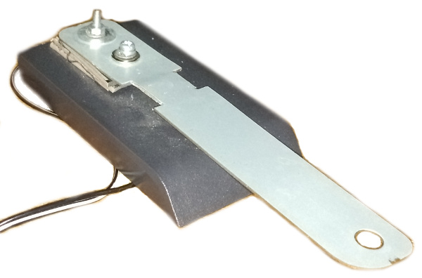
My homebrew code key (sorry about the dust, my son was using it as a toy for a while)
As of this writing, I have NOT yet made any HF contacts (because I didn't have a way to reliably transmit until now). While I listen to the Morse Code section of the 40-meter band all the time on my SB-303 receiver, I'm not yet experienced with the in's and out's of HF CW operating. I know how to send CQ and know (mostly) how to reply to someone sending CQ, but the actual 'meat' of the conversation is a little lost on me. I know you send the BT prosign between thoughts and SK means you're ending the conversation (along with the last two loose 'dits'), but I've never had an HF QSO, ever, so hopefully someone will be patient with me when I finally do reach them.
I recommend putting the completed kit in a shielded metal enclosure or case (or in an Altoids or similar tin, as mentioned earlier). Make sure this kit is connected to a good earth ground and you'll need to use a very clean 9 - 12-volt power supply or a battery within that voltage range. Based on my experiences, any hum or other power-supply noise is greatly amplified in the received audio and will make reception of other stations almost impossible. Also, this transceiver is highly microphonic, so any bumps or vibration will be picked up by the circuitry.
If you are are on a very tight budget like me, you might want to give this kit a try. For the price of a cup of fancy coffee or fast-food lunch, you really don't have much to lose.
Update - 2015-11-24
 It's
still working and hasn't blown up, but the transistor that acts as the power
amplifier gets really hot, so I've stuck some metallic tubing onto its body
to dissipate the heat. I also purchased an inexpensive rechargeable 12 volt
battery to give my transceiver a little more 'kick'. And last but
not least, I put the tiny transceiver into an Altoids tin to protect and
shield it. One of these days I'll either purchase or build a better
transceiver, but for now, I'm making due. It's the budget ham way!
It's
still working and hasn't blown up, but the transistor that acts as the power
amplifier gets really hot, so I've stuck some metallic tubing onto its body
to dissipate the heat. I also purchased an inexpensive rechargeable 12 volt
battery to give my transceiver a little more 'kick'. And last but
not least, I put the tiny transceiver into an Altoids tin to protect and
shield it. One of these days I'll either purchase or build a better
transceiver, but for now, I'm making due. It's the budget ham way! ![]()
If you have any questions, tips or find any inaccuracies, please leave a comment below. Thanks!
Comments
73
Hank
K9lzj
I purchased mine from this (as of this writing) auction and seller:
http://www.ebay.com/itm/321745589972
Thanks for your message!
It looks like a Chinese version of the "Forty9-er", but without seeing the schematic I cannot tell.
I put a link to the Forty-9er but this blog software doesn't seem to allow that.
Depending on how far from 7023 you want to move, you may need to change some of the values in parts of the circuit.
73 - Bill KA8VIT
As far as links in the comments, I had to disable them because of spamming. This is a completely static blog system (completely manual) so I'll try enabling links and see how it goes.
Thanks again for your comment!