Related: Pixie 40-meter transceiver kit
HF CW QRP (low-power Morse code on shortwave frequencies) is very interesting to me, so I've wanted for a while to build my own homebrew stuff and get on the air. The thing is, I don't have a lot of the equipment necessary to successfully build and test home-made equipment. Amateur radio operators are expected to have high quality standards when they make, and use their own equipment. You can't just throw together an oscillator and hook it to an amplifier and that's that. No way.
I did build a sub-$5 USD 'Pixie' kit last year, but it turned out to be dreadful and I didn't feel like customizing it to make it work the way I wanted (I've been going through some health issues the last year, which has frequently depleted any strength I have, including strength to work on radio stuff). I've been watching eBay for an inexpensive Heathkit HW-8 multi-band QRP transceiver, but nothing surfaced in my price range. So the next best thing, an open box MFJ-9340K, was listed for the right price. It arrived not long after my payment and sat on my radio table until I had the time, and strength, to put it together.
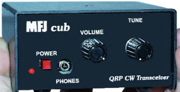
The MFJ-9340K 'Cub' 40-meter QRP CW kit as shown on the
MFJ site
When the kit arrived, it was in a medium-small white MFJ box, carefully packed by 'Carrie' (Thank you Carrie!). All the parts appeared to be present and there were no major blemishes, nicks or scratches on the parts.
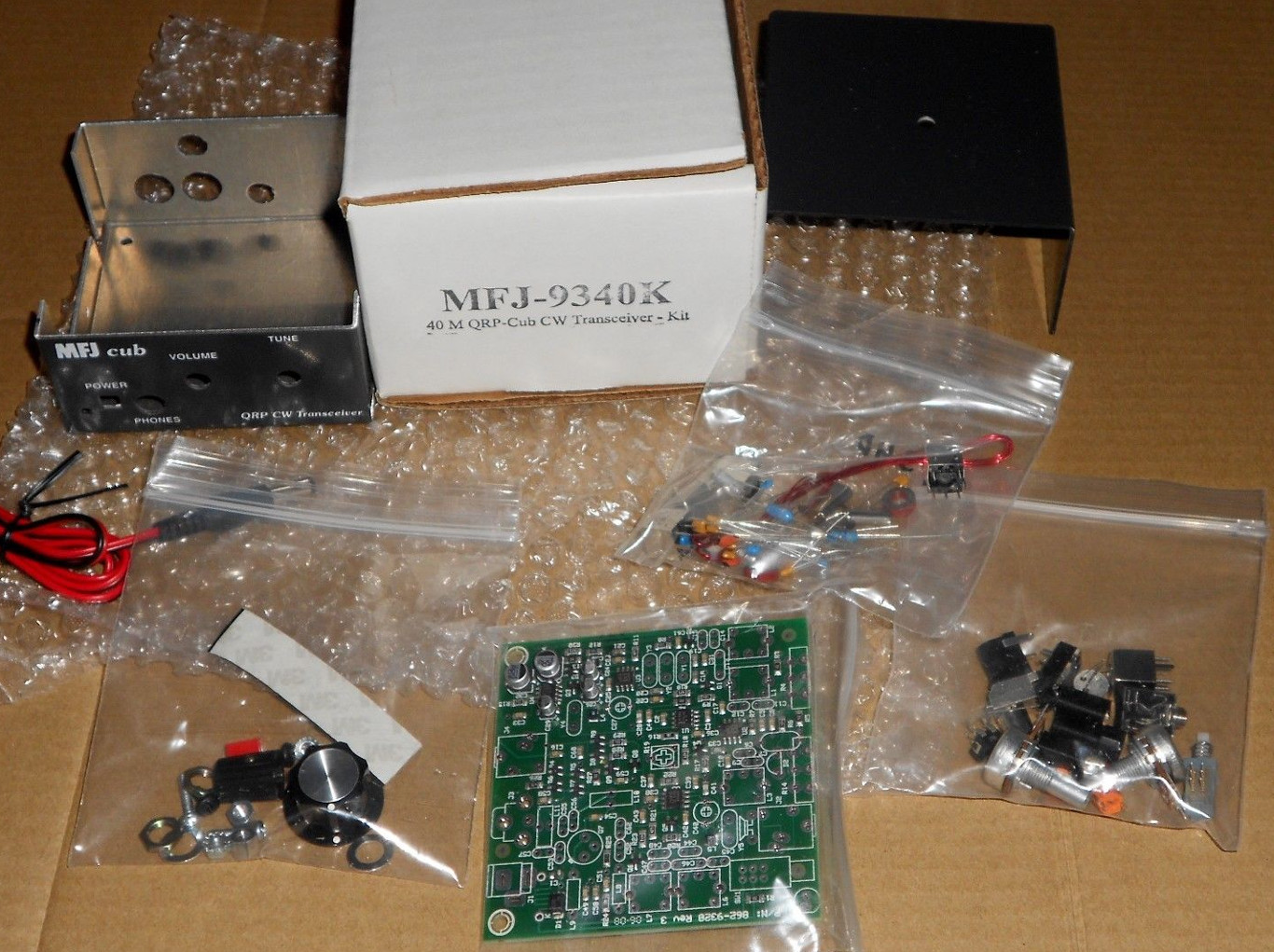
The Cub kit before assembly
If you've ever read reviews about MFJ products, you're probably aware that MFJ has a reputation for being inconsistent. Sometimes MFJ delivers a really good product, sometimes it's all messed up with cold solder joints and hardware banging around loose inside on delivery.
In my case, just about everything was fine except for an SMT (surface-mount technology) capacitor, C1. C1 was not installed horizontally as it should but vertically. Only one conductor of C1 was making contact with the board. The component pick-and-place machine for C1 must have been having a wee problem.
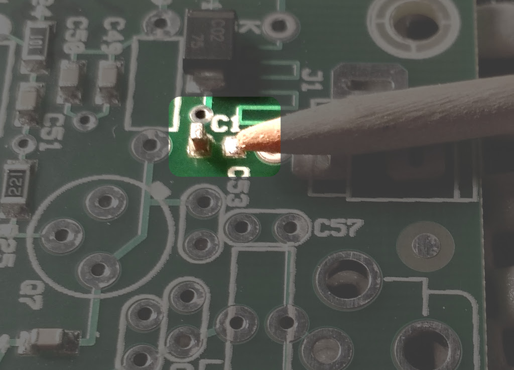
C1 is installed incorrectly on the board (it should
be laying horizontally)
I freaked a little because I thought I'd have to de-solder this small SMT capacitor and then re-solder it to the board properly. I don't have the specialized tools necessary to do SMT rework, so I settled on another solution -- make a simple wire jumper to properly connect C1. Since C1 is not in a critical circuit, I didn't think the wire jumper would cause too much trouble.
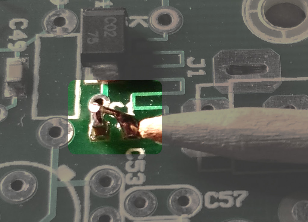
C1 connected using a small wire jumper

The Cub's circuit design is pretty simple, yet there are nice features built-in. It has decent AGC on receive, has acceptable break-in and side-tone is derived from your transmitted signal. A full explanation of how the circuit works is available on YouTube by at least one individual.
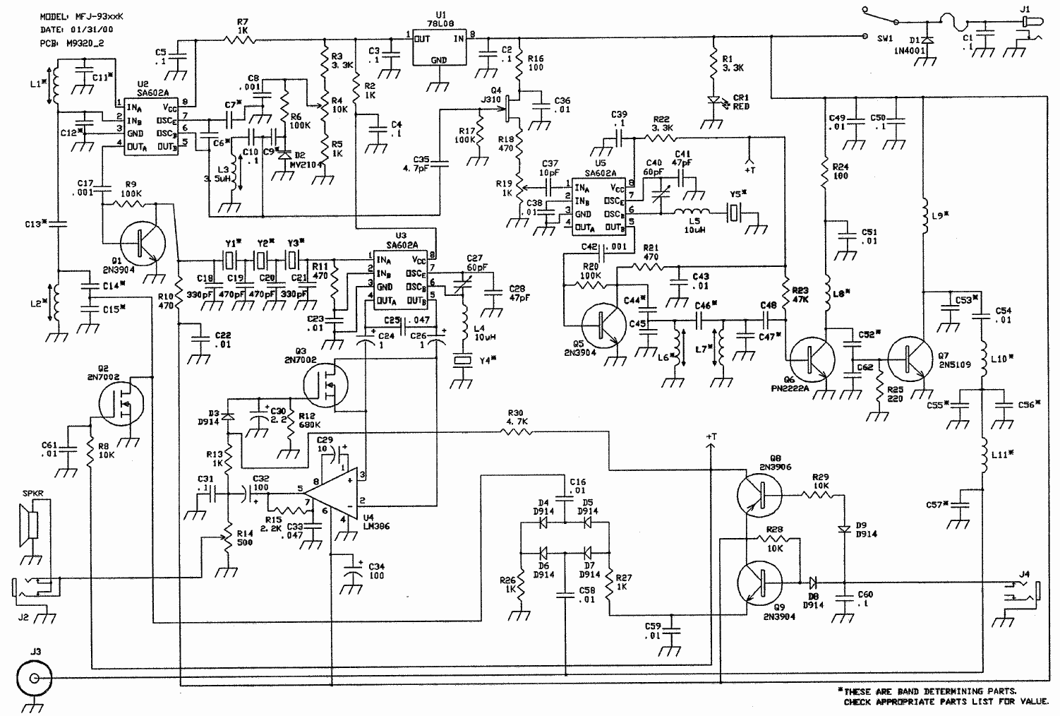
MFJ-93xxK schematic (Note: There is no included
speaker)
Because my kit was an open box, it did not come with the manual but MFJ has that available for download on their site. The instructions were fairly clear and I didn't have too much trouble following along.
First bag of parts installed
I didn't run into any real big snags soldering up this kit. The only difficulties I had were with the RF transformers. They are a little challenging to push into the circuit board because of their pin and tab layout, but after some careful manipulation, they finally stopped being stubborn and pushed down.
With this kit you are required to wind your own toroid coils. This kit has two small toroid coils with eighteen turns on each core. I think most folks don't have a problem winding their own toroids, it's probably just keeping track of how many windings they've done. With larger toroids you can just count using the tip of a pen or toothpick, but with these smaller toroids, it's a little more challenging. It was not terrifying, and I managed to keep my sanity intact.
The instructions warn you of some things to look out for. First, you should make sure you don't push the final amp transistor all the way down onto the board because it needs an air gap to help it stay cool (it does come with a clip-on heat-sink however). You're also cautioned to avoid pushing the crystals down all the way onto the board because the metallic bottom of the crystals might short out the solder pads underneath them.
All parts installed. My workmanship isn't perfect, but it
works!
This kit took about two to three hours to solder up completely. This does not include the time required to align the radio or install the circuit board into the case.
Testing and alignment time
When it comes time to align and test the radio, I highly recommend using non-metallic alignment tools. Using standard metallic screwdrivers is possible, but it will be a frustrating experience. Also, metal screwdrivers could fracture the brittle adjustable slugs in the RF transformers, so it's better to play it safe. There are non-metallic alignment tool sets available for a decent price on eBay. If your Cub kit is like mine, you'll only need various sizes and thicknesses of the non-metallic slot-head screwdriver tools.
For those who don't have specialized equipment, MFJ includes instructions on how to align the radio using fairly conventional means. Thankfully I have an inexpensive Sark 100 antenna analyzer and digital shortwave receiver, which made alignment a breeze. I didn't always have an antenna analyzer, so I'm very grateful for this very helpful tool.
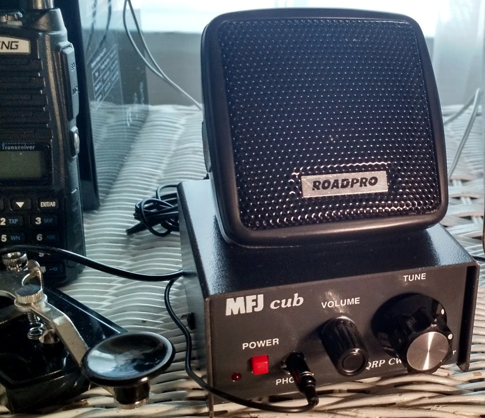
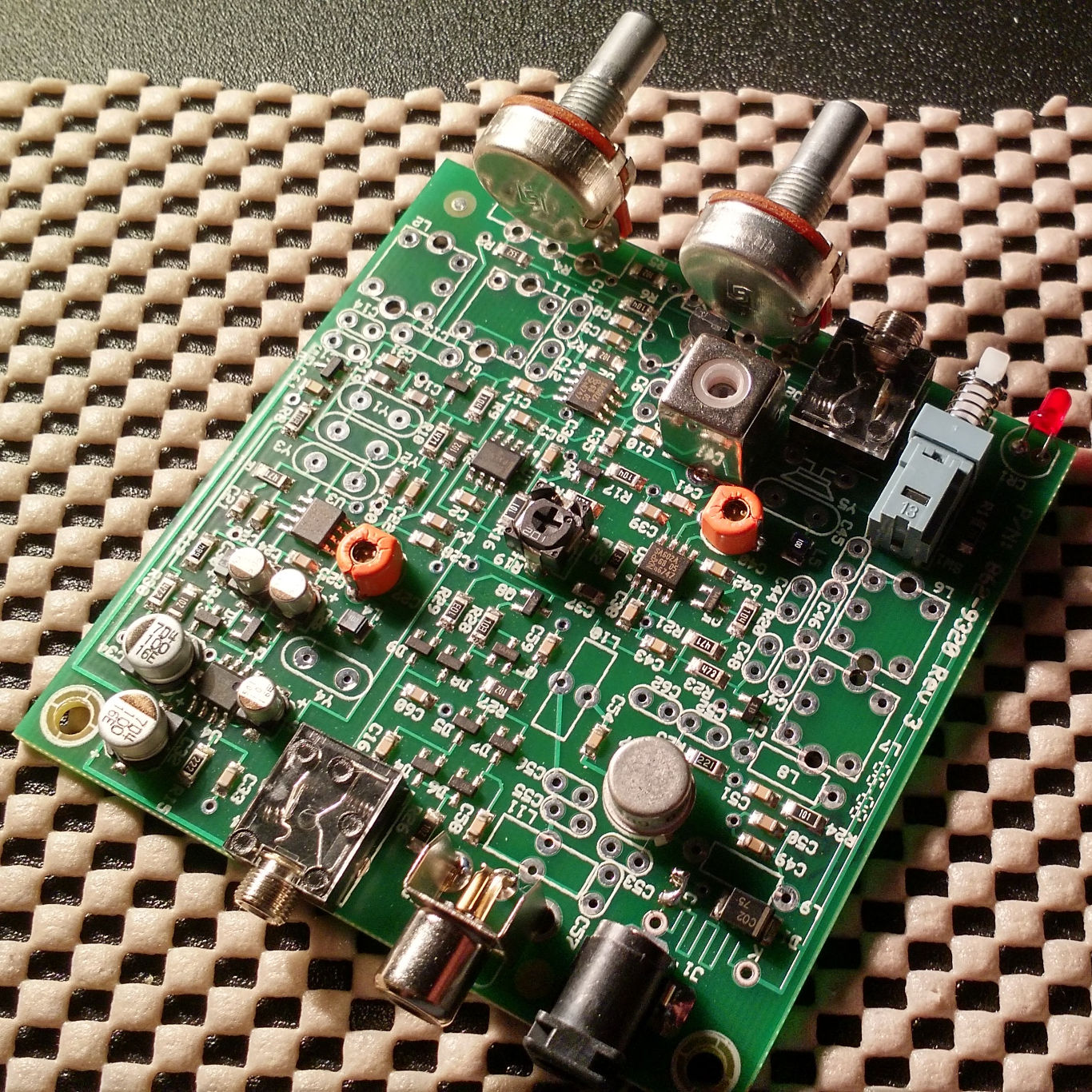
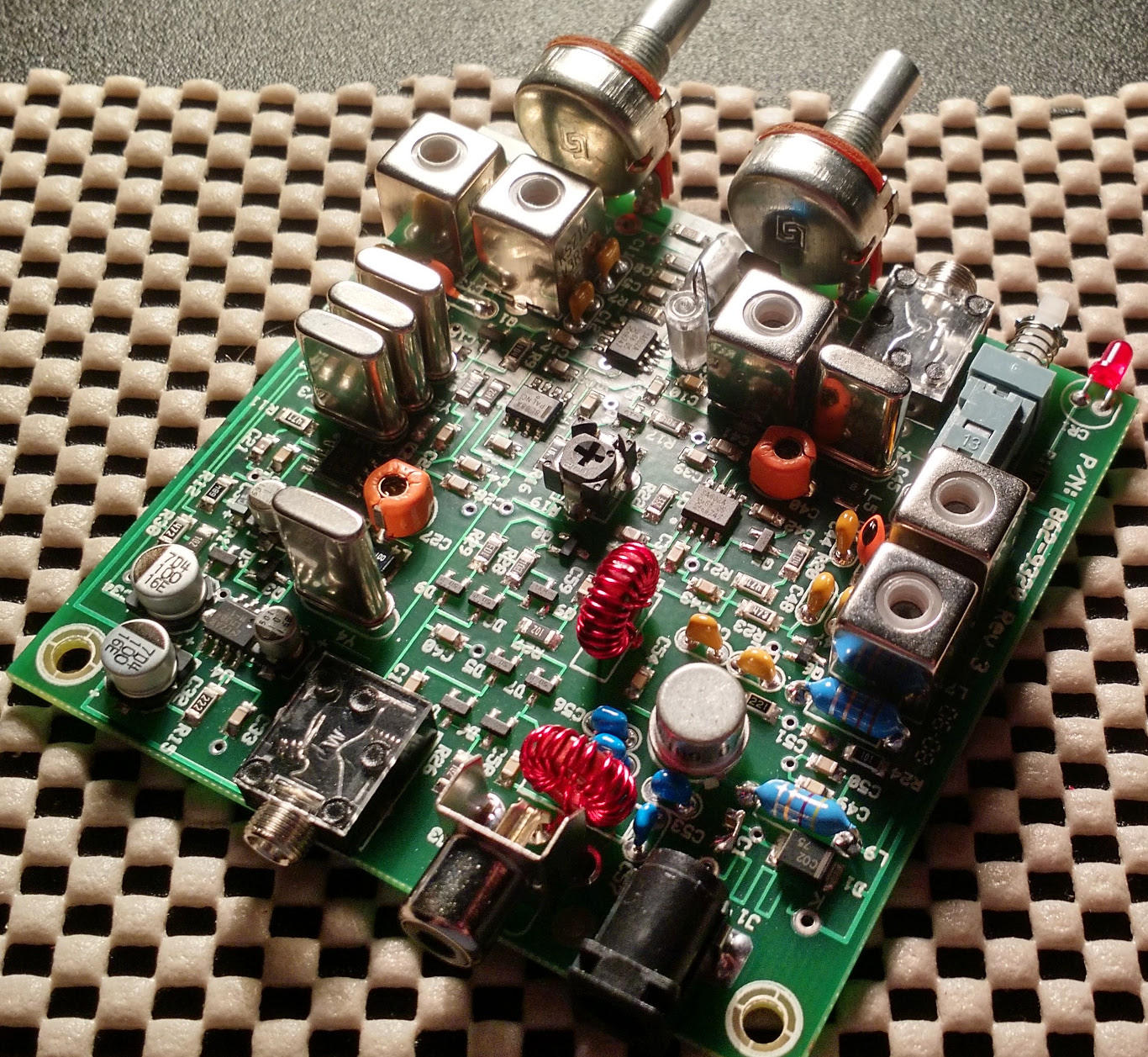
The finished product
After initial alignment and testing, it's time to put the circuit board
into the supplied case. Despite the case being pretty small, there is
plenty of a little room for you to add customizations. While
there is no included speaker, MFJ provides two solder pads on the circuit
board for you to connect your own internal speaker, if desired. I think
I'm going to drill some holes at the bottom of the Cub's case and stick a
small speaker there. The Cub's audio amp does provide enough power to
drive a small speaker to very good volume levels. I put a little computer
CPU thermal paste between the final amp transistor and included clip-on
heat-sink for more reliable cooling.
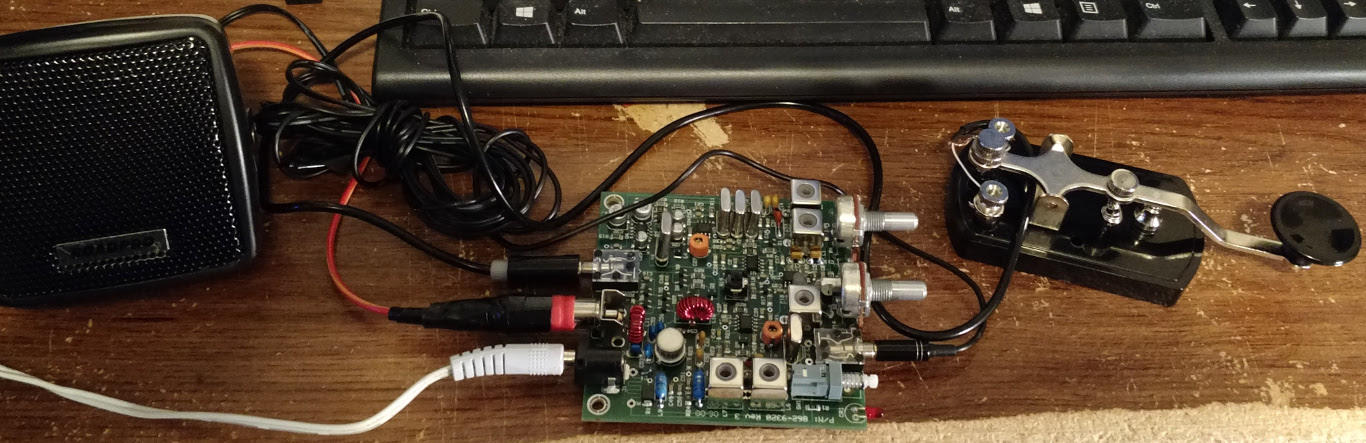
Usage
As mentioned in other reviews, the Cub does have very noticeable drift
when first powered up. After about ten to fifteen minutes the drift starts
to settle down.
Receive audio is good, without too much extra noise. AGC works reasonably well and is just a tad bit slower than most other rigs' 'fast' AGC setting. Tuning is very touchy with the provided knob so the largest diameter knob you can find that will fit the front of the radio is recommended. Even then you sometimes need a feather touch to adjust incoming signals so a replacement ten-turn potentiometer might work better for some folks.
As of this writing, I have not yet made any contacts with this tranceiver. The specifications state that it puts out about two watts of power, which is a huge leap compared to the tiny power my Pixie kit produced. I have a 'compromise' antenna at the moment, but after putting together a homebrew antenna tuner and 9:1 UnUn, I was able to get an SWR of about 1:1.
I tried calling CQ for what seems like hours, with no one answering. I do know that my signal is going beyond the confines of my small town as I pulled up the closest WebSDR server and (intermittently) saw my signal traveling the 310 miles to KC7IGT's receiver in Renton, Washington. Conditions haven't been too great lately, so I'll try again when things get a little better.
The transmitted CW tone sounds very pleasant and doesn't have clicks or chirps. The radio's break-in is acceptable. As mentioned earlier, the side-tone is an attenuated version of the transmitted signal, so you'll have a pretty good idea how your signal sounds to others. I used a large 12 volt rechargeable battery as well as a one-amp 'wall-wart' plug-in 12VDC power supply and the Cub did just fine with both. The Cub seems to sip power, which is great for emergency and / or portable operations.
Overall, the MFJ Cub's circuit design is pretty good. With a minimum of parts you have good receiver and transmitting performance for a QRP rig of this price. And as mentioned earlier, there is a decent amount of space within the Cub's case to add small circuit additions or a built-in speaker.
If you're on an extreme budget and have no other way to get onto HF, the MFJ Cub is a good solution. It's not as fancy as Oak Hills Research's OHR 100A, the Norcal 40 or MFJ's more expensive QRP radios, but it's not some bargain-basement five dollar toy rig either.
Thanks for taking the time to read my post! 73 / 72 and God bless you!
![]()
Update: 2016-07-24
After using the Cub for a while, there
are a couple of things I want to add to this posting.
First, frequency drift is a fairly pronounced problem with this little rig when it's first powered on, as already mentioned. Another thing that causes drift after the Cub has been powered for a while is a bit of physical resistance with the tuning potentiometer. There are spots in the rotation of the tuning pot that cause it to bind up slightly so when you think you've tuned a station successfully it may detune a bit after you release the tuning knob. I imagine after a year or two of use the tuning pot may get a little more worn in and the binding issue won't be so bad. (Note from May 2018: It still has the pot binding problem. Probably a low-quality pot or damaged at the factory)
One other thing to mention is that the receive front end of the Cub is slightly insensitive if not connected to a decent-sized antenna. My Cub often sits next to me on my night-stand as a receive-only radio using an inside antenna that's about five to seven meters in length. My inexpensive Tecsun shortwave radio pulls in stations a bit better with the same antenna than the Cub. If you plan to use the Cub in a receive-only capacity with a relatively short antenna, you might want to construct or purchase an RF pre-amp to boost the incoming signals.
Update: 2018-10-14
The Cub is currently taking a long nap until I can get a replacement phone/speaker
jack. The phone jack included in this kit is cheaply made and isn't really made to
last a long time.
Eventually I'll get the Cub running again, but for now I have my old battered Heathkit SB-303 sitting on my nightstand and I can now enjoy hearing 80, 40, 20 and 10 meters (the other bands are non-functioning due to a broken oscillator coil).
If you have any questions, tips or find any inaccuracies, please leave a comment below. Thanks!
Comments